Thursday 28 November 2013

LIGHTSHIP CORMORANT / LADY DIXON - Chapter 20


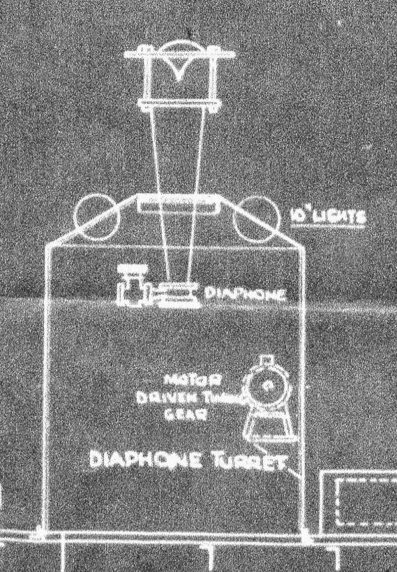
Pursuing the Diaphone research, I joined the Gamewell Diaphone Forum. They seem mainly interested in the more modern train/truck horns, but I did get a helpful response from Jim of California – “I would guess from the drawing of the turret that the ship probably had a Type F or F 2T Diaphone. The vertical horn whose picture you found would have been omni-directional, hence the rotating turret might have been redundant (or perhaps for the lights)”. 
He does own one of these monsters, but in all the years he has been an enthusiast, he has never seen one for sale. So I don’t think we are going to be able to reinstate the capability!

Having guessed that the hole in the main mast was where the shaft of the light adjusting mechanism went through, it did not take Hercule Poirot to work out that there should be a corresponding hole on the opposite side. Simon investigated and not only found the hole in the mast, but also the hole in the bulkhead next to it. 

That hole goes right through the bulkhead, but the blueprints are not clear enough to determine whether the pulley operating the wires/ropes up to the light was in between the mast and the bulkhead, or on the outside of the bulkhead.

Nor can I determine exactly what the wires/ropes do up there at the light.

One other mystery to be solved – directly above where the main mechanism would have been are two pulley wheels set into the roof (sorry, deck). In that position they surely must have had something to do with the light mechanism?


Meanwhile the damn,  sorry damp weather is holding up progress. The main deck needs to be sealed and insulated, but is too wet most of the time. This causes condensation and damp below, so the spray-on insulation down there cannot be applied. Realistically I think that is it for the next few months until the warm weather returns, but Simon can get on with finishing the new kitchen and installing some efficient heating upstairs at least.
David

Monday 25 November 2013

LIGHTSHIP CORMORANT / LADY DIXON - Chapter 19


Well I had never heard of a Diaphone before!  Why didn’t they call it a foghorn, which is what it is in form and function?  Anyway, the plans revealed a ‘Diaphone Turret’ on the roof of the superstructure, just in front of the lantern mast. The structure is about 10ft tall overall and 5ft diameter. As it is called a turret, I assume that it rotates, although I am not sure why. It would explain the ‘MOTOR DRIVEN TURNING GEAR’ label inside the turret – assuming I have interpreted the rather indistinct third word correctly.

The Diaphone can be seen (just) in the 1950s photo of the Lady Dixon on station near Carrickfergus. 

I found a photo of an up-to-date version, which has the ‘deflector’ at the business end, although the noise-generating end has a 90° bend.

The diaphone horn was based directly on the organ stop of the same name invented by Robert Hope-Jones creator of the Wurlitzer organ. Hope-Jones' design was based on a piston which was closed only at its bottom end and which had slots, perpendicular to its axis, cut through its sides; the slotted piston moved within a similarly slotted cylinder. 

Outside of the cylinder was a reservoir of high-pressure air.  Initially, high-pressure air would be admitted behind the piston, pushing it forwards. When the slots of the piston aligned with those of the cylinder, air passed into the piston, making a sound and pushing the piston backwards to its starting position, whence the cycle would repeat.  A modification of Hope-Jones' design was patented by John Pell Northey, who added a secondary compressed air supply to the piston in order to power it during both its forward and reverse strokes and thus create an even more powerful sound, which carried for miles. The entire horn apparatus was driven by a compressor.
There is unfortunately nothing remaining of this wonderful sea organ, but that is probably a good thing as the temptation to try it out would be overwhelming.
David

Thursday 21 November 2013

LIGHTSHIP CORMORANT / LADY DIXON - Chapter 18


Returning to the mystery of the main mast….
We did not know whether the mast extended below the lower deck, or ended on that deck. Now the plans show us that the mast goes right down to the bilges. There is an impressive supporting structure around the mast at the main deck level. The first photo is of this structure taken in Cormorant and viewed on the lower deck. 

The second picture is from Gull (R.I.P.) and taken on the upper deck, where graffiti artists obviously plied their lonely, sad trade. 

According to the various historical documents:-

 There were two openings in the mainmast, one below the deck and another on the level of the lantern when hoisted up. Inside the mast was a ladder which the lamplighters climbed to trim the lamps. Both openings were stiffened round the edges with wrought iron frames.” 
“In this mast were two openings, one below the deck nearly on the fore side, and another on the level of the lantern when hoisted up. Inside the mast was a ladder, up which the men climbed to trim the light when it was mast-headed. The lower opening was 5 feet 3 inches high, and 1 foot 4 inches wide, and was of rectangular form…”

Well there is no evidence of any wrought iron frames anywhere on the remaining piece of mast that stretches between decks, although there are a number of ‘layers’ apparent.

I think that when the original ‘hoist-able’ lamp was replaced by a fixed lamp with outside ladder access, the openings in the mast were welded up to improve strength.
On the plans we can see that one lamp operating procedure was to be carried out remotely and the mechanism for this includes a shaft which goes right through the mast. That steel projection which can be seen pointing towards the camera in the photo above might well be the remains of a supporting bracket for the mechanism and the small circular hole just above it was the entry point for the shaft.


I have enhanced the mast in the side views to make it clearer.
I have yet to work out what this mechanism actually does. It seems to be a manual system, so it would not be anything to do with rotating the light. Perhaps it swivels the mirrors and directs and/or focuses the beam(s).  Are there any experts out there?
David

Sunday 17 November 2013

LIGHTSHIP CORMORANT / LADY DIXON - Chapter 17


Someone has suggested that the protrusion on the bow was indeed an anchor securing point and a similar protrusion can be seen on the old Albatross.  

I agree, but of course the Albatross was a much later vessel and made of steel. Bolting on a protrusion would have been straightforward.
Cormorant's bow was more like that of the Gull, made of wood. 

So I had another look at the photos I took of Cormorant's bow and there is a substantial metal plate fixed onto the two large stanchions.

I did wonder when I took the photos what the plate was for and perhaps this is how they fixed that anchor extension onto the vessel. There is no sign of the extension now.
David

Thursday 14 November 2013

LIGHTSHIP LADY DIXON / CORMORANT Chapter 16


Having solved the mystery of why, in the 1950s photo, Lady Dixon’s stern looked so different from that on Simon’s ship (the boat platform squared it off),  I turned my attention to other mysteries. In that photo, the companionway at the bow seemed to be positioned against the starboard gunwale and faced across the boat, 


whereas on Simon’s ship it is amidships and faces aft.  (Do you notice how these nautical terms are now tripping off the tongue?) 

Anyway, the recently arrived plans have also solved this one. 

What we see in the 1950s photo is in fact a different structure which is shown on the plans containing a loo for the crew and a storeroom. The companionway is indeed amidships and so looking again at the 1950s photo, all becomes clear (I hope).

Another mystery solved but yet another found. What is that projection at the bow?  Does it point forward or sideways?  An anchor or a boat station? Do please comment.
David